
DigitalRooster-Mk3A: Check Your Silkscreen!
I have ordered a new batch of five prototypes of the latest revision of Digitalrooster-Audio Mk3A. The idea was this would be the final prototype before ordering a small batch to sell on tindie.com. This time pcbway assembled most parts manually. They claim they placed and soldered the ICs on the machine but I have my doubts. It makes little sense to me to create a stencil, program the pick-and-place, put 5 PCBs on a SMT line,mount five chips each PCB, go through reflow and later hand-assemble the 40+ resistors and capacitors…. But I am no expert on SMT production. Anyway the super-cap was inverted on the proving pictures they sent, I checked and asked for correction, easy.
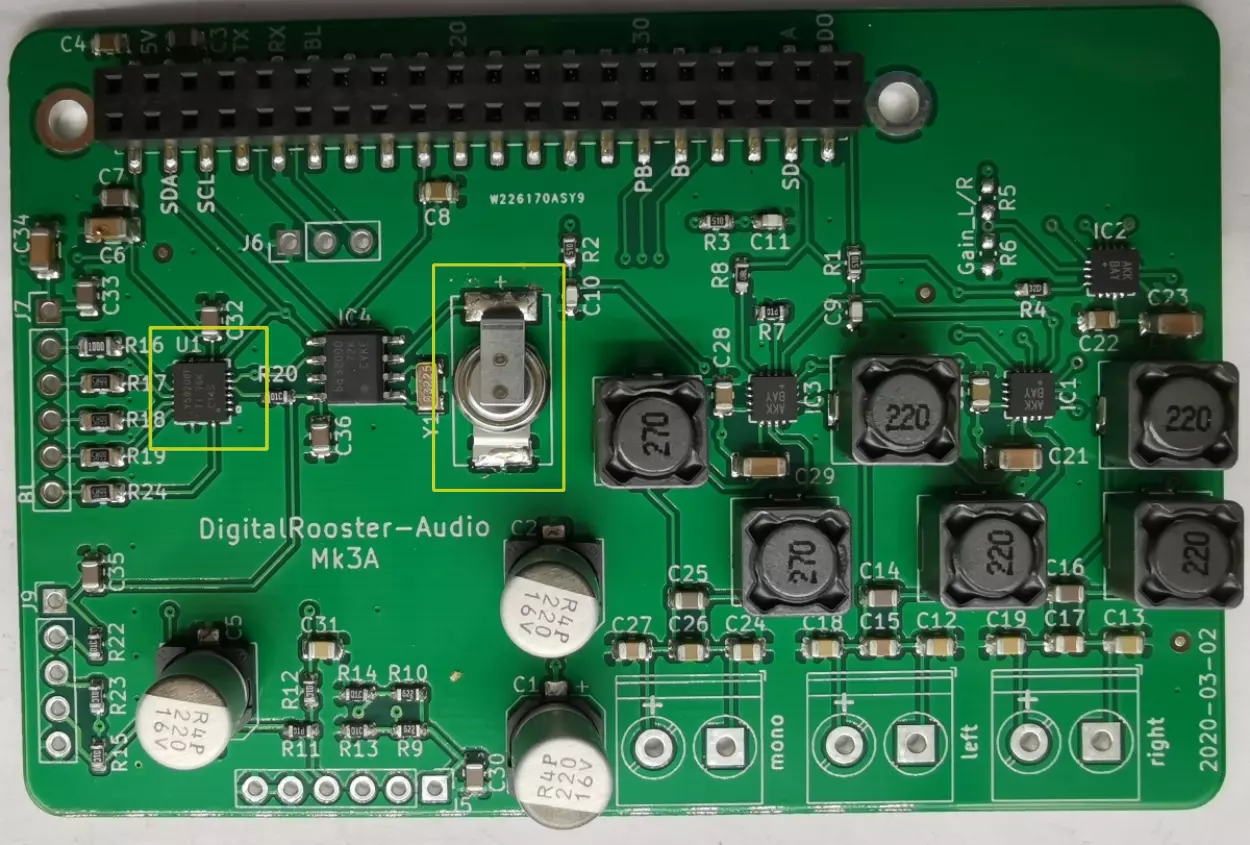
I missed the to check the orientation of U1, the LED driver TLC59208F, it was
turned 180°. This is not pcbway’s fault. I also probably would not have caught
the error. Look at this silkscreen! See where the marking is? Clearly not next
to pin 1.

I got the TLC590208F CAD data from ultralibrarian.com and didn’t event think about the possibility that this could be an issue - I was wrong.
Connecting the PCB to Raspberry Pi short-circuited the 3v3 rail and probably killed the touch controller of one of my displays. But the bug was easy to find the chip got really hot, I almost burnt my fingers. Asking around among my friends, nobody had a hot-air desolder station available. The way to remove the chip was using a common hot-air blower, wrapping the PCB in Aluminium foil. This worked pretty well. Soldering the chip was not that easy for my shaky hands and big solder tip. I had three new chips left, two have been soldered successfully.
In the end I am happy finally I have backlight control PWM on a Banana Pi. I will fix the silkscreen and make some minor layout improvements in KiCad. Some smaller points like matching the APDS9960 connector to match the Adafruit APDS 9960 breakout board and beautification.