Hardware
The initial prototype was built using a Raspberry Pi Zero an Adafruit PiTFT and Speaker Bonnet plus some circuitry on a prototyping PCB. This works but had a range of serious drawbacks. For instance the Speaker Bonnet does not have a GPIO connected to the shutdown pin of the codex which leads to a nasty popping noise when changing tracks. I also required some circuitry to adapt the voltage levels of the rotary encoder to 3.3V, I also wanted a real time clock.
But most important: I have been an electrical engineer since 2008 but I have never designed a PCB this was my chance to learn electronic design!
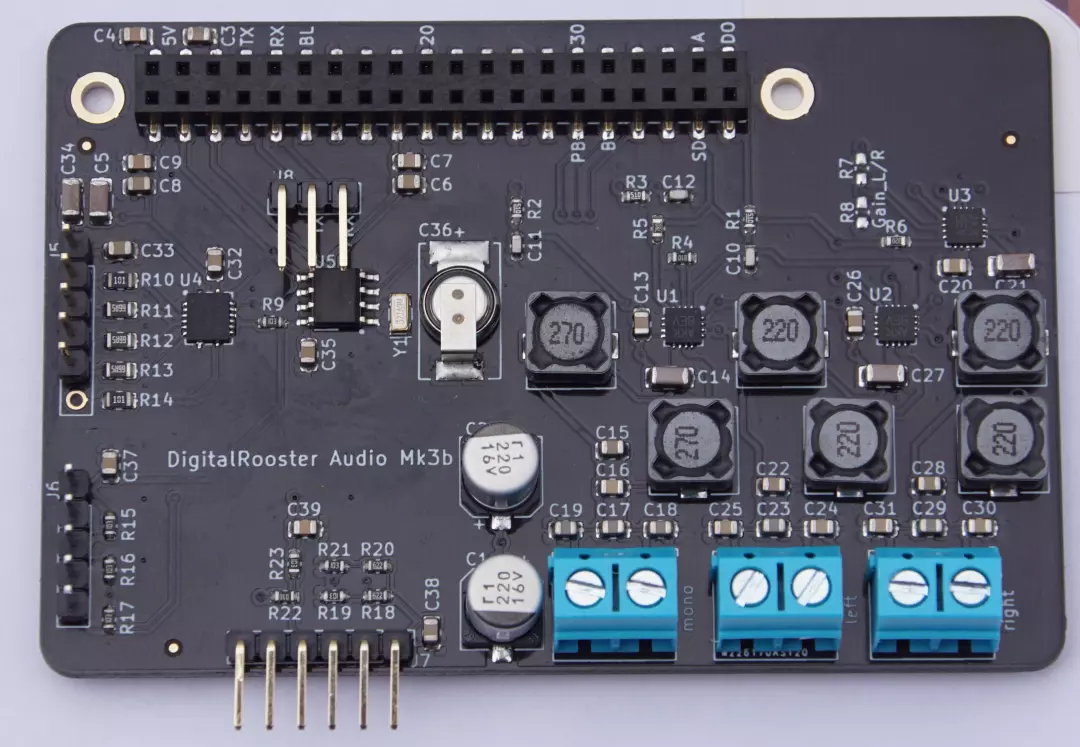
DigitalRooster-Mk3b extension board

The hardware design started in 2019. I was ordering PCBs and imagined hand
assembly for the prototypes. Not only was the design unnecessarily complicated,
it also had a pretty bad layout and I had to admit my soldering skills do more
damage than good. Pcbway’s turnkey assembly was the way to go. However I still
needed two iterations to get what I wanted. Probably an experienced electronics
hardware engineer would find many possibilities for improvement, especially for
layout and component costs. But I am happy so far. With the Mk3b I finally got
the board I wanted.
I also think it is ready for mass production and to share
it with you on tindie.com!
Features
Three Channel audio using a 3W MAX98357A I2S driver. Since this IC is a Class-D amp I equipped the channels with passive LC filter to improve audio quality. The left/right channels have a cut-off frequency of around 20kHz while the mid channel filter is a 16kHz low-pass
a hardware shutdown line for the audio codecs so ‘off’ is really ‘off’ and there is no popping noise when changing tracks
A BQ32000 Real Time Clock chip with trickle-charge circuit that charges a 200mF Super-Cap. Although the software synchronizes time using NTP I wanted a Real Time Clock in case the network is down. Also having a the correct time during boot makes logging a lot more insightful and avoids TLS error for certificates that are not yet valid on Jan 1st of 1970…
A TLC59208F PWM LED driver for back-light control and a possible RGBA light to wake up with a sunrise simulation. The PWM pins on both Raspberry Pi and Banana-Pi are scarce an used for other functions, e.g. I2S. Software PWM is not really a nice option so I was willing to spend some 2.5$ for a nice I2C chip that integrates nicely with the Linux LED driver framework
Integrated circuitry for the Grayhill rotary encoder that requires voltage dividers and a debounce for the push button
The possibility to connect an external I2C device. I have a APDS9660 gesture and light sensor in mind for dynamic back-light control or gesture snooze.
Last but not least: a separate header for UART console since when assembled it is hard to access the UART of the Raspberry Pi.
The Mk3b is also compatible with both Raspberry Pi and Banana Pi M2 Zero. So you have a wider choice of more powerful hardware! However Banana Pi M2 Zero performance is sub-par. It takes ages for the display to react to touch events. I don’t consider the Banana Pi version production ready yet. The Raspberry Pi configuration works really nicely.
Note: The Mk3b-extension board is a module without independent function and is exclusively intended for development purposes under laboratory conditions. For use or operation specialist knowledge is required. Please also read the safety and environmental notes
For details please refer to the schematic-mk3b.pdf and the product mk3b landing page mk3b
Where to buy
Currently I am selling a kit that requires some soldering on tindie.com!
Other Parts
To build your DigitalRooster you will need some more parts in addition to the extension board:
Raspberry Pi Zero W (without soldered header)
Adafruit PiTFT2.8” capacitive touch
Note: there are two types sold under the same name:
one with buttons (Mfg Part No. 2423) and without buttons (Mfg Part No. 1983)
I use the 1983 without buttons (Digikey 1528-1423-ND)Long (15mm) 2.54mm connection header to stack the extension boards on the Raspberry Pi (Digikey 3M156504-72-ND)
Grayhill rotary encoder 61C11-01-08-02 (Digikey GH6102-ND)
Kilo International knurled knob OEDNI-90-3-5 (Digikey 226-4201-ND)
Some small speakers ca.3-5W 4Ω for instance Adafruit Speaker
I added links to digikey.com, but they serve only as reference you can get them wherever you like. I do not have any deal with Adafruit or digikey, I just use it because it is convenient.
The total cost is about 120 US$(on digikey) while the rotary encoder alone accounts for 25 US$. You can use different components but these are the ones I have successfully used so far.
If you find a nicer rotary-encoder with push-button that turns even smoother please let me know! I would like one that turns ‘notch-less’
Assembly
I created a photo-sequence with some hints on how to assemble the electronic parts see the page assembly
Casing

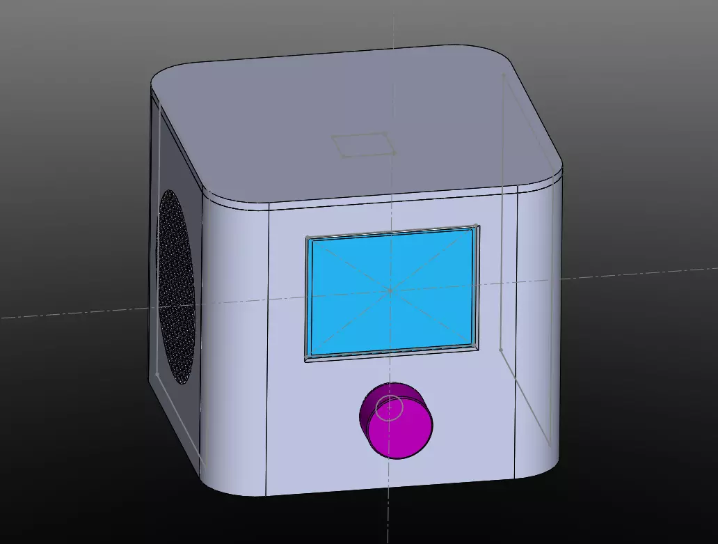
The housing is printed on a Prusa MK3. You can find the
STL-files here.
Make sure you scale the housing with about 0.5% so the side panels fit in
otherwise you will have problems mounting.
